A Simple Approach to Interactive Free-Form Shape Deformations
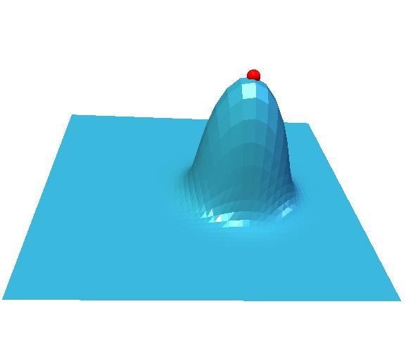
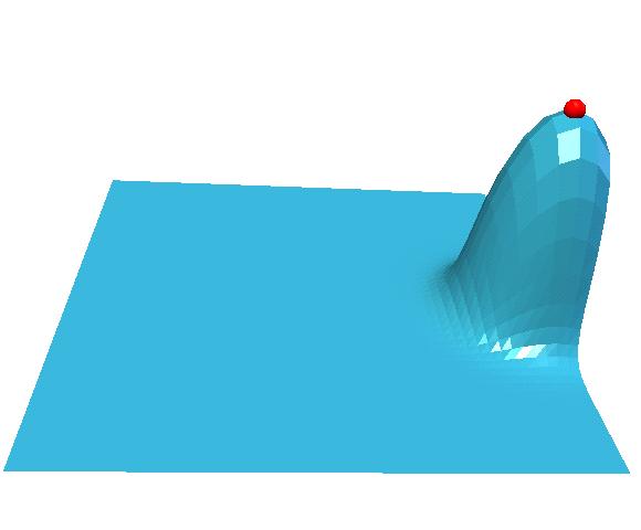
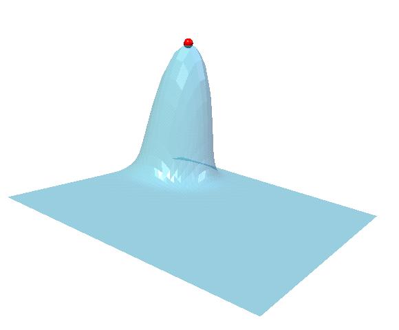
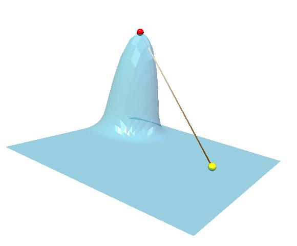
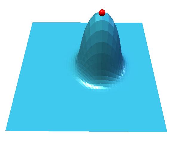
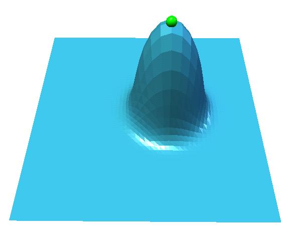
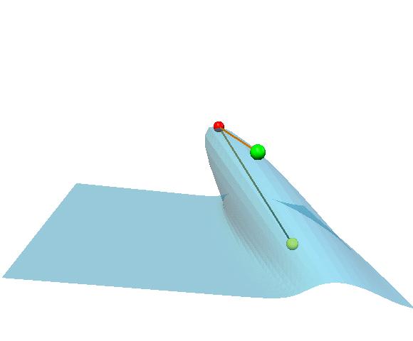
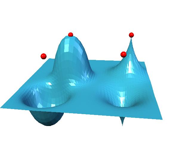
In this paper, we propose a set of free-form shape deformation
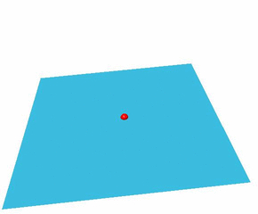
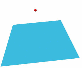
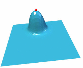
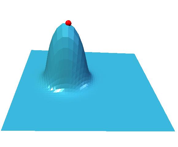
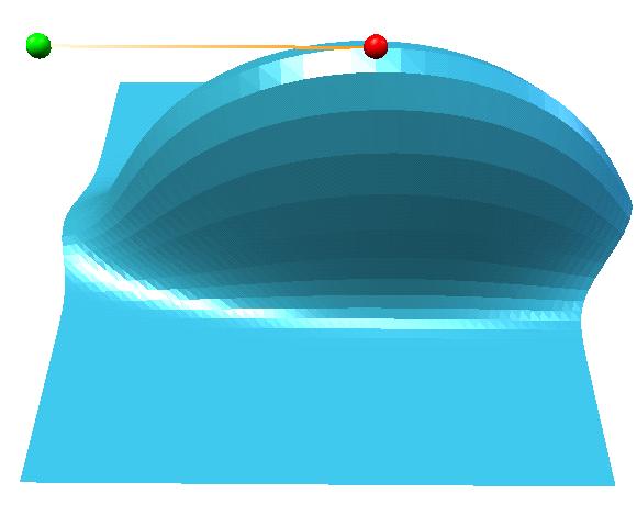
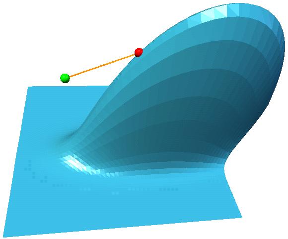
techniques. The basic technique can be described as
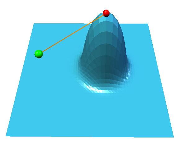
follows. Given a surface represented by a mesh and a control
point, for every mesh vertex let us consider the difference
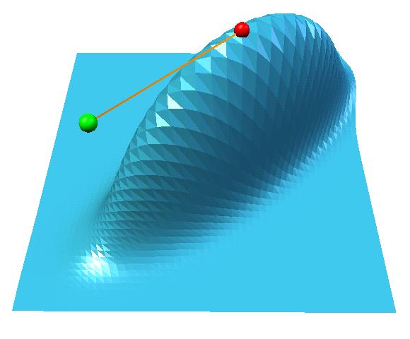
between the control point and the vertex. The vertex is shifted by
a displacement equal to the difference times a scale factor where
the scale factor is given by a function depending nonlinearly on
the difference. The function is bump-shaped and depends on a
number of parameters. Varying the parameters leads to a rich
palette of shape deformations. The proposed techniques include
also shape deformations with multiple (real, auxiliary, and virtual)
control points and constrained, directional, and anisotropic deformations.
We demonstrate how that the proposed set of techniques
allows a user to edit a given shape interactively and intuitively.
The techniques use no mesh connectivity information and, therefore,
can be applied directly to a shape given as a cloud of points.
This research is collaborated with Prof. Dr. A. G. Belyaev and Prof. Dr. H.-P. Seidel. The paper was published in Proc. Pacific Graphics (PG'02), pp. 471-474, October 9-11, 2002 at Beijing, China.
Java3D Free-Form Shape Deformator
You can download the jar file of the Java3D Free-Form Shape Deformator. Also Java3D source files of the Deformator are available. Questions and Bug report are welcome to my e-mail: shin[_at_]riken.jp.
- You need the JDK (after 1.1) and
Java3D API environment.
- Please download the java application jar file, and apply "java
-jar DeformationMesh.jar". To avoid
OutofMemoryError use "java -mx800m -ms800m -jar
DeformationMesh.jar", for example.
- Polygonal data have to be constructed by the PLY2
format. To enjoy our simulator, you can download the sample
polydata, and a few
interesting polydata which is used for our numerical experiments.
- Please see the simple manual.
Copyright
All rights are reserved by Shin Yoshizawa. This java codes are allowed
for only a primary user for research and educational purposes. Don't use
secondary use: copy, distribution, diversion, business purpose, and etc.. In no event shall the author be liable to any party for direct, indirect,
special, incidental, or consequential damage arising out of the use of this
program and source files.
Commercial and Business Use
If you would like to use this Java sources in your commercial software then please contact with me and RIKEN.
Simple Manual
How to use
- Manual 1: Basic Deformation Process
- 1: Input Original Mesh: "file"->"load (poly2)". Please select the PLY
format polydata.
- 2: Add control points:
- 2-1: Choose "add" in 2th row of control
panel, see Figure 2 which is organized in Manual 3.
- 2-2: Click the original mesh. Of course, you can click many
times for multiple control points when now and after deformations.
- 3: Move the control point with updating manually:
- 3-1: Choose "no" in 2th row of control
panel, see Figure 2.
- 3-2: Drag the control point.
- 4: Update Deformation Manually: Push "E-Net" button of control
panel.
- 3: Deformation updating automatically:
- 3-1: Choose "no" in 2th row of control
panel, see Figure 2.
- 3-2: Select an appropriate sleeping time for animation thread
by "Th. Sleep".
- 3-3: Push "Start Animation" button of the control panel.
- 4: Move the control point with updating automatically:
- 4-1: Drag the control point.
- 4-2: Add more control points, or change parameters, or use
advanced deformations.
- 4-3: If you satisfy the deformation, Push "Stop Animation"
button of the control panel.
- Manual 2: Advanced
Deformation Options: A few examples of how to use the advanced deformation options is represented in the following figures.
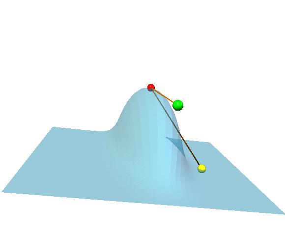
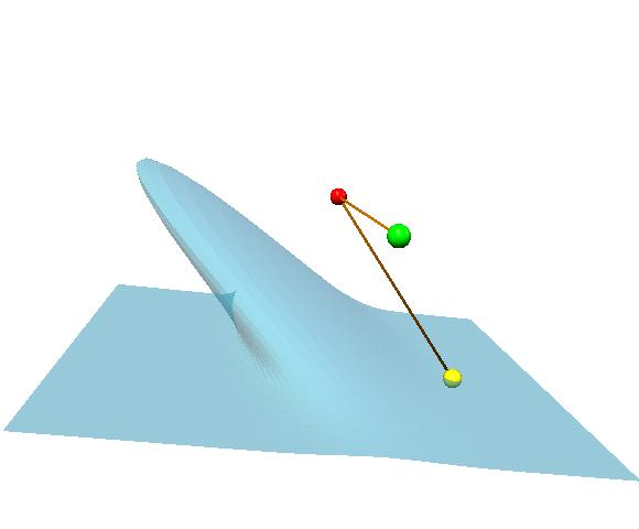
- Multiple Control Points: You can increase the control
points. Also, you can see and change the selected (last clicked
control point) each parameters and type of the control points on
the control panel and the scroll bars, see Figure 2 and 3. In
the other word, these states and parameters are changed when you
click the other control point.
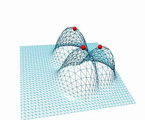
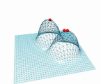
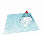
Moreover, You can select the overlapping effect or blending
(union) effect for the multiple control points by selecting
"Edit"->"blending" of menu bar, see Figure 1.
- Constrained Control Point and Static/Dynamic
Distance Field:
- 1: add the control point.
- 2: select "Edit"->"Ref. Vis".
- 3: change the control point type from "v" to "cv".
- 4: change the distance field from dynamic "w" (ON) to static "w" (OFF).
- 5: You can move the control point.
- 6: Also, you can move the reference point on the original mesh.
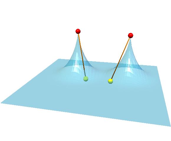
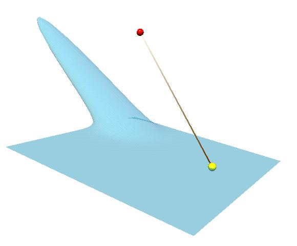
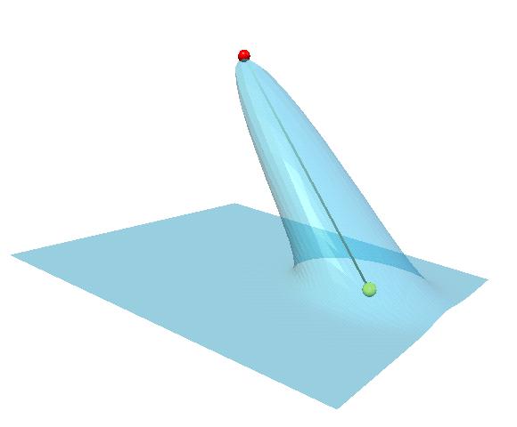
The advantage of
using dynamic distance field ("w"->ON) is that the deformation which is more sensitive
about the shape features than using static distance field
("w"->OFF) can be achieved.
|
Dynamic Distance Field: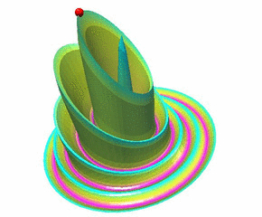
|
|
Static Distance Field: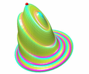
|
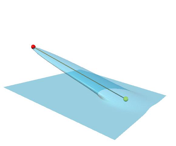
- Anisotropic Distance Measurement:
- 1: add the control point.
- 2: select "Edit"->"Ani. Vis".
- 3: move the anisotropic reference point with the tangent plane restriction.
- 4: update the deformation.
- 5: move the anisotropic reference point, and update its deformation.
- 6: move the anisotropic reference point, and update its
deformation via "Edit"->"Ani. Constrained" (OFF)
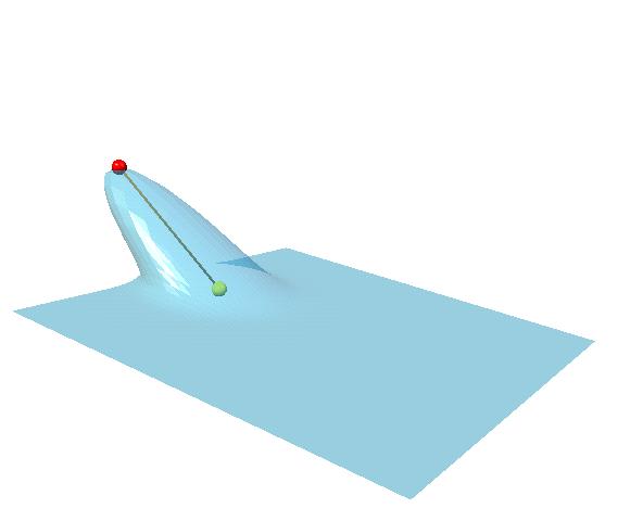
- Anisotropic Constrained Case:
- 1: add the control point, select "Edit"->"Ref. Vis" and
"Edit"->"Ani. Vis", and move the anisotropic reference point.
- 2: change the control point type from "v" to "cv".
- 3: change the distance field from dynamic "w" (ON) to static
"w" (OFF).
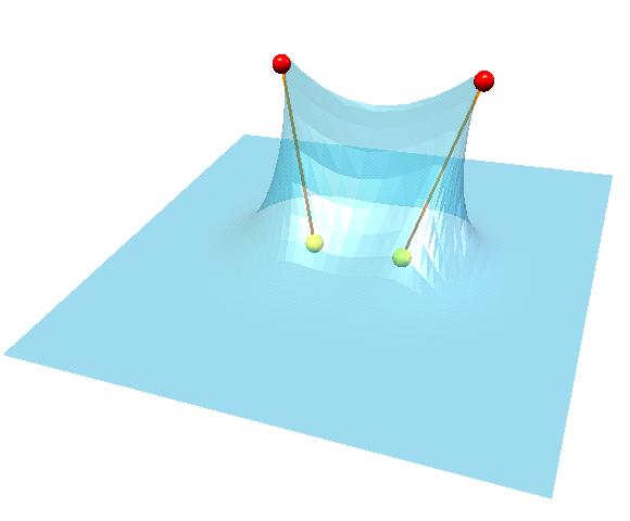
- Creases Deformation:
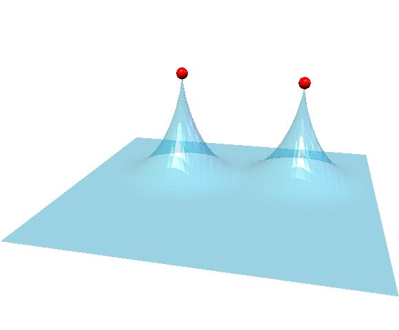
- 1: make two sharp attractings via two standard control points
with gamma = -1.
- 2: change both control point types from "v" to "cv", and
select "Edit"->"Ref. Vis.".
- 3: change both distance fields from dynamic "w" (ON) to static
"w" (OFF).
- For the creases deformation, please note that the distance
between both reference points have to be smaller than the
distance between both control points.
- Manual 3: Functionally Instructions
- Menu Bar: Menu bar is located on the top of the 3D Mesh Deformation simulator.
Figure 1: Menu Bar:
 |
- file:
- exit program: quit the simulator.
- load: load(poly2): load polydata file.
- save(poly2): save the deformed mesh to the PLY format file.
- save image(.jpg): save the canvas to the JPG format file.
- Deformation Mesh:
- Normal color: change coloring to a standard coloring.
- M-curvature-Pastel: change coloring to a mean curvature
pastel coloring.
- WireFrame: change to a wireframe.
- Points: change to a cloud points.
- 2 Lights: additional lights ON/OFF.
- Back Face: back face rendering ON/OFF.
- Material Light: material lighting ON/OFF
- transparency: transparency HALF/FULL. We recommend the
back face OFF when you use the half-transparency.
- Edit:
- Ref. Vis.: The reference points are visualized by
the yellow color spheres when the control point is added and ON
(true). Also, you can drag the reference point on the mesh.
- Ani. Vis.: The anisotropic
reference points are visualized by the green color spheres
when the control point is added and ON (true). Also, you can drag
the anisotropic reference point on the tangent plane of its
control point.
- Ani. Constrained: For the last clicked anisotropic
reference point, the tangent plane restriction of its
anisotropic reference point is available when ON (true). You can
avoid this restriction by selecting OFF (false) for the last clicked anisotropic
reference point.
- par. change all: If this check button is ON (true), you
can change the epsilon, alpha and gamma parameters of all control
points for same value.
- blending: Blending effect when ON (true) and overlapping
effect when OFF (false) can be selected for the multiple control points.
- Camera: change different camera positions. However you
can change the object and the control points by Left-Drag (Rotation), Center-Drag (Zoom),
and Right-Drag (Transition).
- Th. Speed: change a sleeping time for updating the
deformation thread. The high sleeping time is available for large
data. For example, 500 sleeping time is available
for 50000 vertices mesh, and 20 sleeping time is available
for 500 vertices mesh.
- Control Panel:
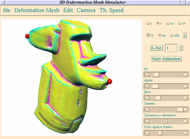
Figure 2: Control Panel:
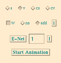 |
- 1st row of Figure 2: type of the last clicked control point: if you
click the another control point, this row is updated by his type
of control point.
control point
- s: choose a standard control point.
- v: choose a virtual control point.
- cs: choose a constrained standard control point.
- cv: choose a constrained virtual control point.
- 2st row of Figure 2:
- w: For the last clicked control point; The dynamic distance field is selected when
ON (true). The static distance field is
selected when OFF (false).
- no: You can drag the control point by your mouse when
"no" is ON. We We recommend the static
distance field for the constrained control point.
- add: You can add the control point by clicking the mesh
when "add" is ON.
- i: Initialize the control points. All control points
are removed by pushing this button.
- 3st row of Figure 2:
- E-Net: One update process is applied.
- I: Initialize deformations. You will get the original
mesh by pushing this button.
- 4st row of Figure 2:
- Start/Stop Animation: Start/Stop a thread for deformation
updating by selected sleeping time. The deformation is updated by
every sleeping time.
- Scroll Bars:
Figure 3: Scroll Bars:
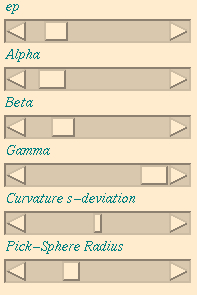 |
- ep: For the last clicked control point, the epsilon
parameter (influence region) can be changed by this scroll
bar.
- Alpha: For the last clicked control point, the alpha
parameter (influence shape) can be changed by this scroll
bar.
- Beta: For the blending of multiple control points, the beta
parameter (blending shape) can be changed by this scroll
bar.
- Gamma: For the last clicked control point, the gamma
parameter (influence size) can be changed by this scroll
bar.
- curvature s-deviation: Threshold for the mean curvature
pastel color mapping on the mesh.
- Pick-Sphere Radius: For the picking control points, the
radius of the control points, the reference points, and the
anisotropic reference point is changed by this scroll
bar.
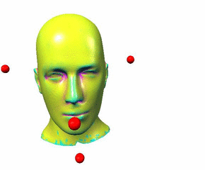
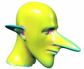
Gallery
Pinokio Mannequin-Head model|
  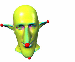
|
New hairstyle and mouth
opening for Mannequin-Head model
|
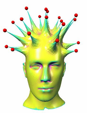
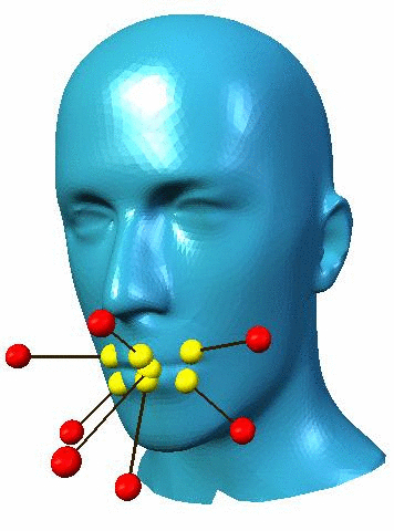
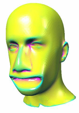
|
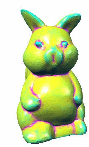
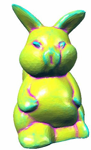
Morphing a squirrel into
a pig-bunny
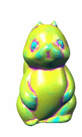
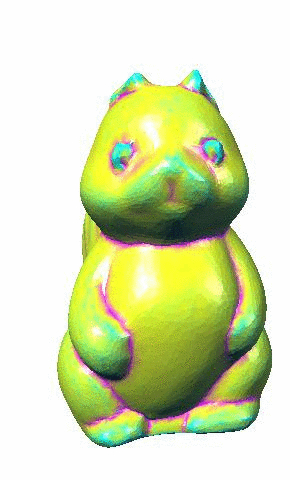
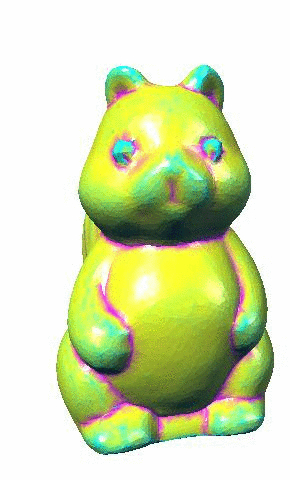
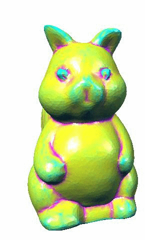
|
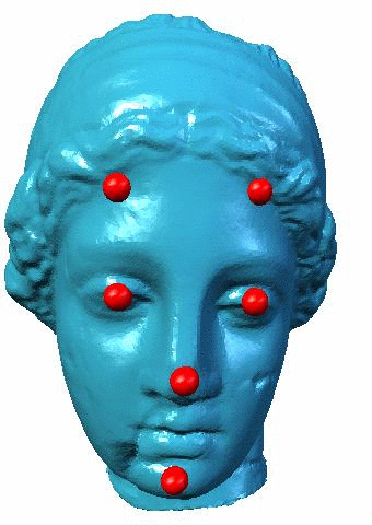
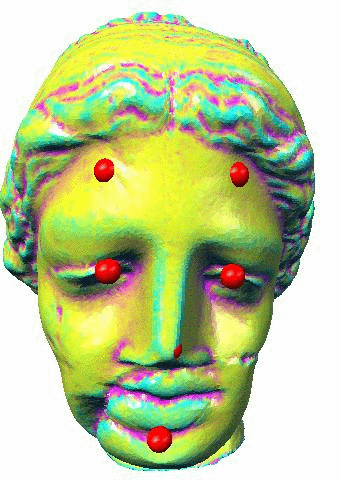
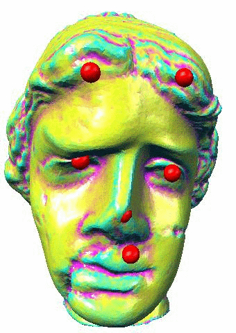
Changing facial
expressions of Venus-Head
|
|
Log
- March, 10, 2016: Source files are uploaded.

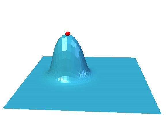
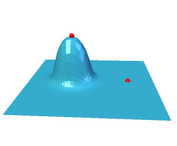
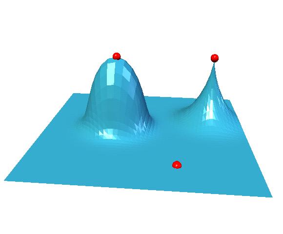
 Overlapping
 Blending
