    |
Ion irradiation for cell surgery with glass capillary
| We present here a cell surgery scheme involving
selective inactivation or disruption of cellular structures.
Energetic ions are injected into a cell through a tapered glass capillary like a microinjection method. A slight but essential difference from microinjection is that a thin window is prepared at the outlet so that no liquid material can flow in or back through the outlet while still allowing energetic ions to penetrate into the cell. An ~MeV He ion beam from such a capillary having 10 mm outlet diameter inactivated a selected volume (mm3) of fluorescent molecules located in a HeLa cell nucleus. |
|
Y. Iwai et al., Appl. Phys. Lett. 92 023509 (2008). [html] |
|
Cell surgery’ using nano-beams (RIKEN RESEARCH, 26 March 2010). [html] |
|
|
||
|
Volkhard Mäckel, Puttaraksa Nitipon, (Tokihiro Ikeda#), Takao M. Kojima, |
| Atomic Physics Laboratory, RIKEN |
|
Naoko Imamoto |
| Cellular Dynamics Laboratory, RIKEN |
|
Kazuhiro Maeshima |
| National Institute of Genetics |
|
Tadashi Narusawa, (Takuya Nebiki) |
| Kochi University of Technology |
|
Grigory P. Pokhil |
| Skobeltsyn Institute of Nuclear Physics, Moscow State University |
|
* (Persons) left.
|
Microbeams for biological cell
| A typical animal cell is about 50 mm in diameter, composed of complex intracellular organelles and assembled macromolecules, which range in size from more than 1 mm (e.g. chromosomes, mitochondria, and nuclear compartments) down to 100 nm (e.g. centriole, and nuclear pore complex) or less. Several research groups have been intensively working on the preparation of ~MeV microbeams for biological applications. | |||
| In a conventional scheme, a well-focused energetic ion beam is extracted in air via a vacuum isolation window, then injected into a biological cell in water.1,2) Another straightforward scheme involves passing energetic ions through a micron aperture with or without a thin window at the end.3-5) | |||
|
Drawbacks of these schemes are;
(A) a relatively large cylindrical volume is damaged along the beam trajectory in addition to the targeted point, (B) serious energy and angular stragglings are induced during passage through the vacuum isolation window and air, which deteriorates the beam quality, and as a result determines the lower-limit of the beam size at the target, and (C) real-time control/monitoring of the bombarding point is not easy even when a micrometer beam is prepared. |
|||
| References | |||
|
1) |
G. Dollinger et al., "Microirradiation of cells with energetic heavy ions", Nucl. Instr. and Meth. B 231, 195 (2005).[html] | ||
|
2) |
M. Hess et al., "Targeted Irradiation of Mammalian Cells Using a Heavy-Ion Microprobe", Radiat. Res. 165, 231 (2006).[html] | ||
|
3) |
G. Randers-Pehrson et al., "The Columbia University Single-Ion Microbeam", Radiat. Res. 156, 210 (2001). [html] | ||
|
4) |
M. Folkard et al., "The design and application of ion microbeams for irradiating living cells and tissues", Nucl. Instr. and Meth. B 210, 302 (2003).[html] | ||
|
5) |
Y. Kobayashi et al., "Irradiation of single mammalian cells with a precise number of energetic heavy ions – Applications of microbeams for studying cellular radiation response", Nucl. Instr. and Meth. B 210, 308 (2003).[html] | ||
Pinpoint energy deposition
| To overcome such technical but serious problems, we have developed a scheme using a tapered glass capillary with a thin window at its outlet.6,7) This scheme can realize pinpoint energy deposition and three dimensional selection of the bombarding point by observing the outlet through a microscope with a precision of a micron or better in an arbitrary position of a living cell or in any liquid object. | |||
| References | |||
|
6) |
T. Nebiki et al., "Focusing of MeV ion beams by means of tapered glass capillary optics", J. Vac. Sci. Technol. A 21 1671 (2003).[html] | ||
| 7) | T. Ikeda et al., "Production of a microbeam of slow highly charged ions with a tapered glass capillary", Appl. Phys. Lett. 89 163502 (2006). [html] | ||
Experimental setup
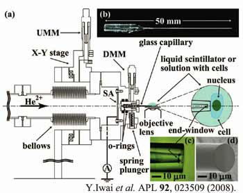
| Figure 1(a) shows a drawing of the microbeam preparation setup including an X-Y stage, which is aligned by the upstream micrometers with respect to the beam line. The beam is first trimmed by a square aperture of 1x1 mm2 formed by four rectangular aluminum plates, then injected into a tapered glass capillary on a capillary holder and passed through a thin window at the outlet of the capillary. | |||||
|
|
|||||
|
|
|||||
| This end window enables the whole beam line to be kept under vacuum and, at the same time, a microbeam can be injected into a liquid target in a well-defined position in front of the capillary. The tapered glass capillary is ~50 mm long (Fig. 1(b)) with inlet and outlet diameters of 0.8 mm and several micrometer, respectively.6,7) The downstream micrometers are used to align the capillary to the beam axis with a step of 0.5 mrad. | |||||
|
The capillary outlet is placed in the focus of an optical microscope, which is installed on a three-dimensional stage. Figures 1(c) and 1(d) show an optical microscope image and a scanning ion microscope (SIM) image near the capillary outlet, respectively. As expected, this window was vacuum tight and the outlet could be safely dipped in liquid. |
|||||
Visualization of pinpoint energy deposition
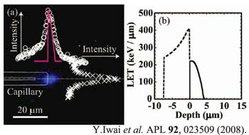
| Ion beams of 3 and 4 MeV He2+ from an electrostatic tandem accelerator at Kochi University of Technology were charge state selected by an analyzing magnet, and then transported to the microbeam preparation setup described above. Figure 2(a) shows a microscope image observed by a charge-coupled device (CCD) camera when a 3 MeV He2+ beam was injected in a droplet of liquid scintillator (BICRON BC-501A) through a tapered glass capillary with a thin window. A diffuse blue area is clearly visible downstream of the window showing ions were injected into a volume of about mm3 in the liquid scintillator through the thin window. | |||||
| The open circles and the crosses in Fig. 2(a) show the observed scintillation intensity projected along and perpendicular to the beam axis, respectively. Figure 2(b) shows the simulated energy deposition in the window and in the scintillator by the computational code "stopping and range of ions in matter," SRIM-2006.8) The thick red solid line in Fig. 2(a) shows the scintillation intensity distribution evaluated taking into account the conversion efficiency from the energy deposition to the scintillation. | |||||
|
|
|||||
|
|
|||||
| Reference | |||||
| 8) | J. F. Ziegler, computer code SRIM-2006.01. (http://www.srim.org/) | ||||
Density enhancement
| The focusing factor x, the ratio of the beam density at the outlet to that of the inlet was measured as a function of the outlet diameter Dout in the range of 1.5 - 9.6 mm. The transmitted ion current was measured with a Faraday cup covering the capillary outlet. On the other hand, the incident current entering the capillary was evaluated by replacing the tapered capillary with a Faraday cup having the same inlet diameter as the capillary. It was found that x increases monotonically like x proportional to Dout-1.3, and reached as high as 1000, which is another important aspect of the tapered glass capillary as compared with a conventional scheme employing a simple aperture. | |||
Cell irradiation
| As the second demonstration, a real biological cell, a HeLa cell whose nucleus was labeled with a fusion protein of histone H2B and green fluorescent protein9) (GFP) was bombarded by a microbeam. The microbeam was prepared by 4 MeV He2+ incident on a tapered glass capillary with an end window of 7.3 mm in thickness and outlet diameter of 9.6 mm (see Figs. 1(c) and 1(d)). | |||||
|
|
|||||
|
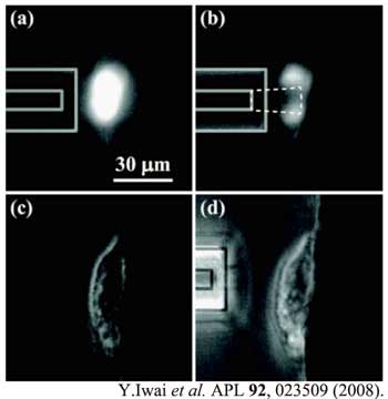
Figure 3: Fluorescent images of a HeLa cell nucleus labeled with histone H2B-GFP.9) (a) Before irradiation and (b) after irradiation by 4 MeV He2+ beam entering a tapered glass capillary with an end-window thickness of 7.3 mm and outlet diameter of 9.6 mm. (c) and (d) are the phase contrast images of (a) and (b), respectively. Solid and dashed lines show an outline of the capillary and a calculation of the energy deposition region by SRIM-2006. In (c) and (d), the capillary is away from the cell to prevent sticking together. |
|||||
| Figures 3(a) and 3(b) show the fluorescence images of the nucleus before and after irradiation for transmitted current of ~100 pA and ~7 s, respectively, which clearly show that the bombarded volume was optically inactivated without affecting global cell morphology (see phase contrast images in Figs. 3(c) and 3(d) before and after bombardment). | |||||
| Reference | |||||
| 9) | H. Kimura et al., "Kinetics of Core Histones in Living Human Cells: Little Exchange of H3 and H4 and Some Rapid Exchange of H2B", J. Cell Biol. 153, 1341 (2001).[html] | ||||
Summary
| We have demonstrated that a tapered glass capillary with a thin end window can deposit energy in a well-selected volume of microscopic region in a cell. A tool enabling "surgery" in an arbitrary region of a cell is now available, providing a technique to study various functions of intracellular structures independently. | |||
| According to the simulations performed by SRIM-2006, the bombardment region can further be reduced, e.g., down to 100 nm or so when a 20 keV He2+ beam is injected in a tapered capillary with an end-window thickness of 100 nm and an outlet diameter of 100 nm.10) The combination of a low energy ion injector and an optical microscope would provide a desktop cell surgery system. | |||
| This work was partly supported by Human Frontier Science Program and a Grant-in-Aid for Scientific Research (No. 17654079) from the Ministry of Education, Culture, Sports, Science, and Technology, Japan, a Grant of Special Projects for Basic Science of RIKEN "Development and Applications of Exotic Quantum Beam," and a RIKEN's FY2006 DRI Research Grant. | |||
| References | |||
|
1) |
G. Dollinger et al., Nucl. Instr. and Meth. B 231, 195 (2005).[html] | ||
|
2) |
M. Hess et al., Radiat. Res. 165, 231 (2006).[html] | ||
|
3) |
G. Randers-Pehrson et al., Radiat. Res. 156, 210 (2001). [html] | ||
|
4) |
M. Folkard et al., Nucl. Instr. and Meth. B 210, 302 (2003).[html] | ||
|
5) |
Y. Kobayashi et al., Nucl. Instr. and Meth. B 210, 308 (2003).[html] | ||
|
6) |
T. Nebiki et al., J. Vac. Sci. Technol. A 21 1671 (2003).[html] | ||
| 7) | T. Ikeda et al., Appl. Phys. Lett. 89 163502 (2006). [html] | ||
| 8) | J. F. Ziegler, computer code SRIM-2006.01. (http://www.srim.org/) | ||
|
9) |
H. Kimura et al., J. Cell Biol. 153, 1341 (2001).[html] | ||
|
10) |
T. Kaito, U.S. Patent No.6740368 (25 May 2004). | ||
| Modified, 6/Feb/2013 by |
| Back |
Copyright (c) 2007-2013 Atomic Physics Laboratory, RIKEN. All rights reserved. |